Free Quote
Welcome to inquire about our products!
Schematic diagram of superconducting magnetic energy storage (SMES) system. It stores energy in the form of a magnetic field generated by the flow of direct current (DC) through a superconducting coil which is cryogenically cooled. The stored energy is released back to the network by discharging the coil. Table 46.
The schematic diagram of the battery is represented in Figure 5 7. The aforementioned carbon-free redox battery type design for both Li-ion and polymer suspension based cell have been explored by
Download scientific diagram | Schematic diagram of Li-ion battery energy storage system from publication: Journal of Power Technologies 97 (3) (2017) 220-245 A comparative review of electrical
The 1-MW container-type energy storage system includes two 500-kW power conditioning systems (PCSs) in parallel, lithium-ion battery sets with capacity equivalent to 450 kWh, a controller, a data logger, air conditioning, and an optional automatic fire extinguisher. Fig. 4 shows a block diagram.
However, with the rapid development of energy storage systems, the volumetric heat flow density of energy storage batteries is increasing, and their safety has caused great concern. There are many factors that affect the performance of a battery (e.g., temperature, humidity, depth of charge and discharge, etc.), the most influential of which
It explores various types of energy storage technologies, including batteries, pumped hydro storage, compressed air energy storage, and thermal energy storage, assessing their
Sodium–Sulfur (Na–S) Battery. The sodium–sulfur battery, a liquid-metal battery, is a type of molten metal battery constructed from sodium (Na) and sulfur (S). It exhibits high energy
CSU (Container 2) – Storage system: a) standard Hy‒COMP XT HP skid for analog signals controlling the compression of hydrogen at the air–driven gas booster; b) air–driven gas booster; c) storage tanks with a total volume of 200 L; d) schematic of the air
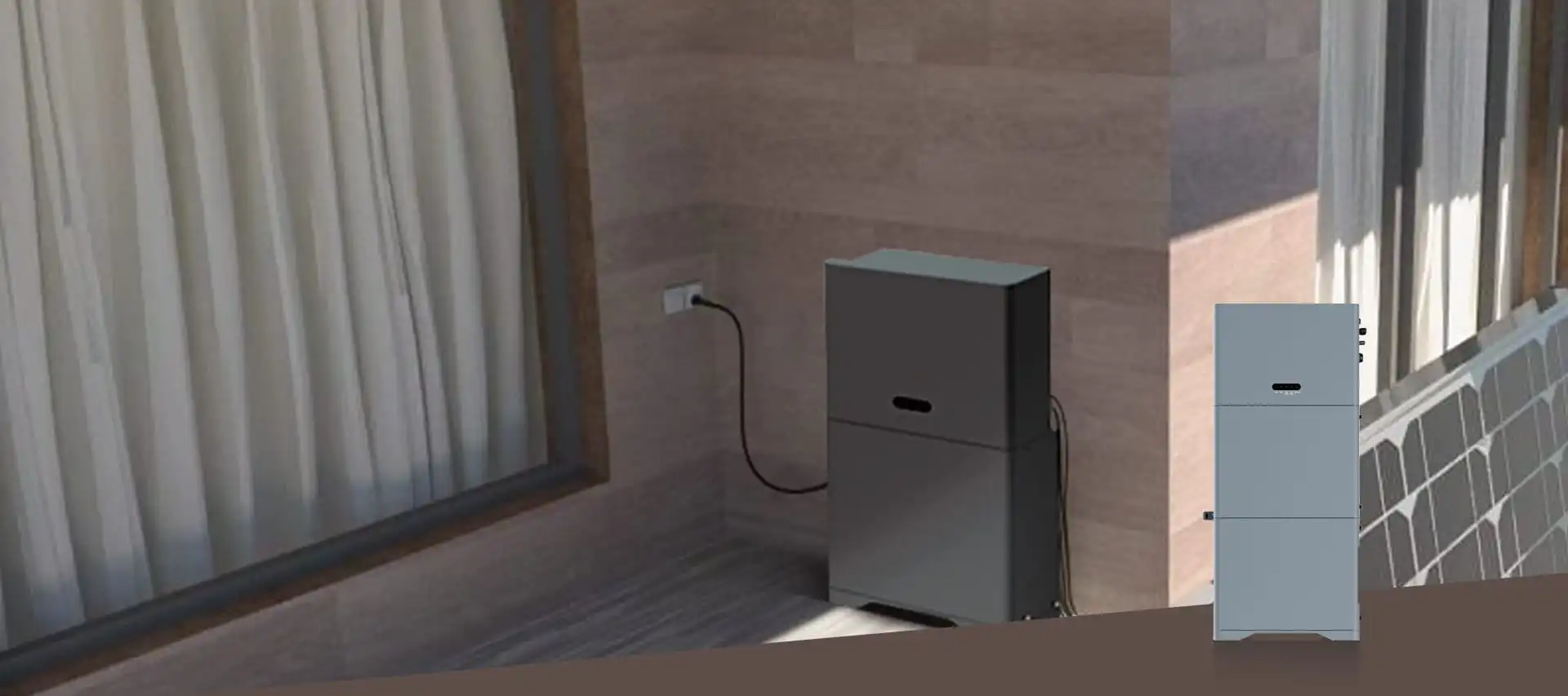
Energy storage system plan design 1.1 Schematic diagram of energy storage container plan 1.2 Battery Cluster Design Schematic 2.2 Battery cell 2.2.1 Battery cell technology parameters SMS Energy
system urea–sodium acetate trihydrate has been mentioned in the literature as an energy storage system. heat by the PCMs. Fig. 1 shows a view for the solar storage container (flat-plate
A Battery Energy Storage System (BESS) significantly enhances power system flexibility, especially in the context of integrating renewable energy to existing
Download scientific diagram | Schematic diagram of a battery energy storage system (BESS) operation, where energy is stored as chemical energy in the active materials,
The second commercial CAES plant, owned by the Alabama Energy Cooperative (AEC) in McIntosh, Alabama, has been in operation for more than 15 years since 1991. The CAES system stores compressed air with a pressure of up to 7.5 MPa in an underground cavern located in a solution mined salt dome 450m below the surface.
Download scientific diagram | Schematic diagram of the grid-connected hybrid energy system. from publication: Multi-Objective Sizing Optimization of a Grid-Connected Solar–Wind Hybrid System
The existing energy storage applications include individual energy storage (IES) and shared energy storage (SES). Risk-based optimization for facilitating the leasing services of
Energy Storage Systems. Last Updated: Apr 18, 2024 Storage Systems. The transition to renewable energy sources, electrification of vehicles and the need for resilience in
Alexander White. A thermal energy storage system where heat is transferred to a cylindrical packed bed along the radial coordinate is described. The governing energy equations and various
Abolghasemi et al. [34] described the thermodynamic analysis of thermal energy storage (TES) system underneath the consequence of nanoparticles combined with PCM or the operational liquid.
Pumped hydro energy storage is the major storage technology worldwide with more than 127 GW installed power and has been used since the early twentieth century ch systems are used as medium-term storage systems, i.e., typically 2–8 h energy to power ratio (E2P ratio).h energy to power ratio (E2P ratio).
The Battery Management System (BMS) collects measurements data from the electrochemical storage and it is responsible for balancing the cells'' voltage, protecting them from overloading, and for
Currently, flywheels and hydrogen technol- ogies are not commonly used for energy storage because of their estimated high cost, which is directly connected to storage time (200-500$ per kW for 5
Battery racks can be connected in series or parallel to reach the required voltage and current of the battery energy storage system. These racks are the building blocks to creating a large, high-power BESS. EVESCO''s battery systems utilize UL1642 cells, UL1973 modules and UL9540A tested racks ensuring both safety and quality.
They are the most common energy storage used devices. These types of energy storage usually use kinetic energy to store energy. Here kinetic energy is of two types: gravitational and rotational. These storages work in a complex system that uses air, water, or heat with turbines, compressors, and other machinery.
Maintaining the grid frequency within acceptable limits ensures reliable and resilient power supply. With the advancements in energy storage system (ESS) technology, including battery Energy
System Description. Currently, a battery energy storage system (BESS) plays an important role in residential, commercial and industrial, grid energy storage and
Thermal energy storage (TES) technologies in the forms of sensible, latent and thermochemical heat storage are developed for relieving the mismatched energy supply and demand. Diverse TES systems
The demand for energy storage systems (ESS) using batteries is increasing for the storage of new and renewable energy [1], Schematic diagram for the ESS. Download : Download high-res image (188KB) Download : Download full-size image Fig. 2. (a) Side
The partnerships between businesses, universities, and governments can also play a significant role to build a sustainable energy economy and to commercially deploy the sustainable energy systems
Thermal energy storage (TES) using phase change materials (PCMs, for latent heat storage) is a key technology in improving efficiency of Concentrated Solar Power Plant (CSP) where solar heat can
Flowchart Maker and Online Diagram Software. draw.io is free online diagram software. You can use it as a flowchart maker, network diagram software, to create UML online, as an ER diagram tool, to design database schema, to build BPMN online, as a circuit diagram maker, and more. draw.io can import .vsdx, Gliffy™ and Lucidchart™ files .
Temperatures can be hottest during these times, and people who work daytime hours get home and begin using electricity to cool their homes, cook, and run appliances. Storage helps solar contribute to the electricity supply even when the sun isn''t shining. It can also help smooth out variations in how solar energy flows on the grid.
This paper reviews the selection, strengthening, and application of PCMs and containers in latent thermal storage system for solar air‐conditioning systems. The optimization of PCM container
Welcome to inquire about our products!